Select deep dive mode to read the background of the previous and current design.
Introduction
While looking for a way to access the SWD/JTAG pads on the back of my XIAO board, I couldn't find a solution that suited what I needed. Existing options were either feature-rich development platforms like the XIAO Debug Mate or required soldering directly to the board. I wanted something much simpler like a holder or clip that could be attached or removed in seconds while still providing reliable SWD access.
Parts
To build this clamp, you will need the following parts:
- 4x Pogo pins (CPG-69-TH-B)
- 1x Pen spring
- 1x SWD breakout board
- 28AWG wire
- Double-sided tape
- Cable tie (optional)
- PLA, ASA or PETG filament (and a 3D printer of course)
Making it
To begin, you need to solder wires to your Pogo Pins and then thread each pogo pin from inside the clamp through the four holes. The wires should come out the bottom and then run up along the stem to a position you believe would be right for your SWD breakout board. I chose the very end of the clamp where you push the two sides together, this was not a great spot, I suggest you place it closer to the pins.
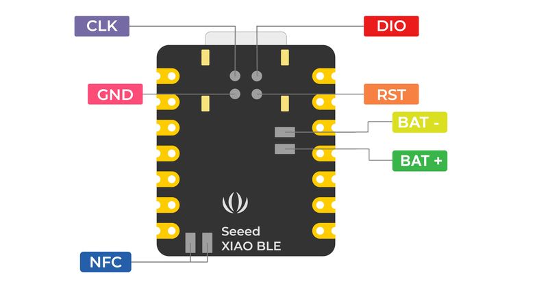
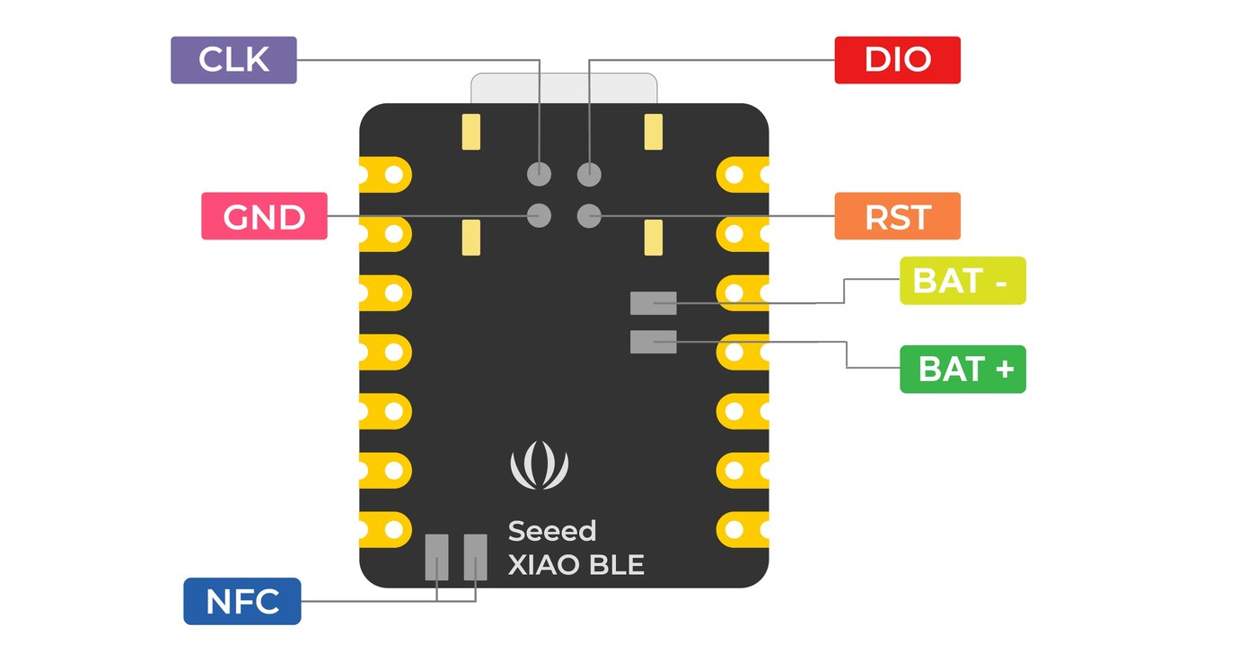
Each wire should be soldered correctly on the SWD breakout board. On the back of the Xiao nRF52840, there are 4 JTAG pads as shown below.
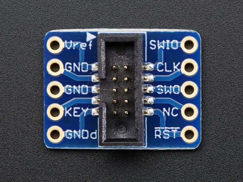
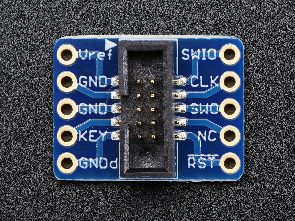
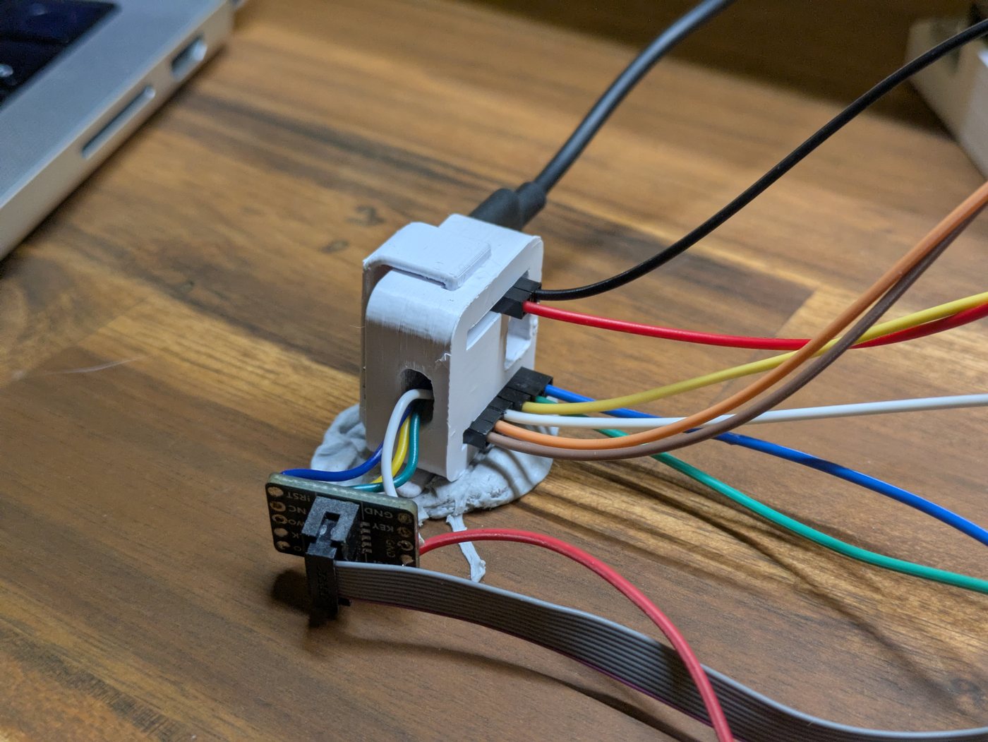
The breakout board will look like this (image shown above):
(1) Vref    (2) SWIO
(3) GND     (4) CLK
(5) GND     (6) SWO
(7) KEY     (8) NC
(9) GND     (10) !RST
The pins should be wired as follows (Xiao --> Adafruit Breakout Board)
| Xiao Pads | Adafruit Breakout |
| CLK | CLK (4) |
| DIO | SWIO (2) |
| GND | GND (3) |
| RST | !RST (10) |
| 3v3 | Vref (1) |
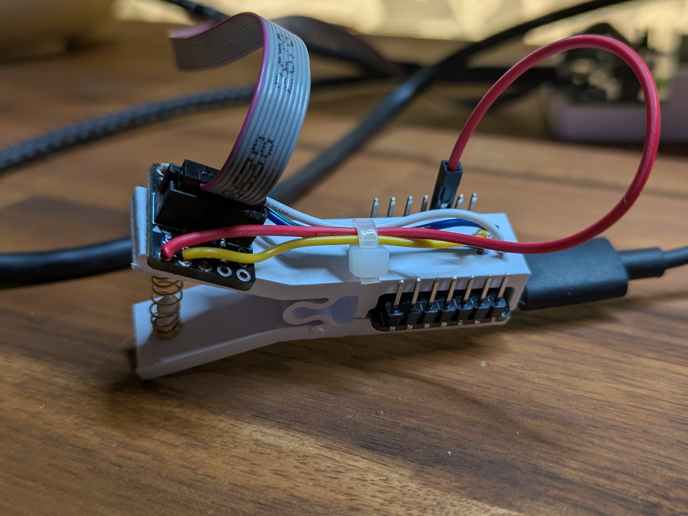
After soldering all the pins, you can then use double sided tape to attach the SWD breakout board to the clamp. You can choose to use a cable tie to hold the wires together, it also helps to protect them from breaking off from movement overtime.
When it comes to connecting Vref to the Xiao, I cut the end from a dupont jumper lead giving me a female connector. This allows me to switch between connecting directly to the 3v3 pin on the Xiao and connecting to a breadboard. Versatility is everything.
Your final clamp should look something like this, if it doesn't... try again?
The Original Design
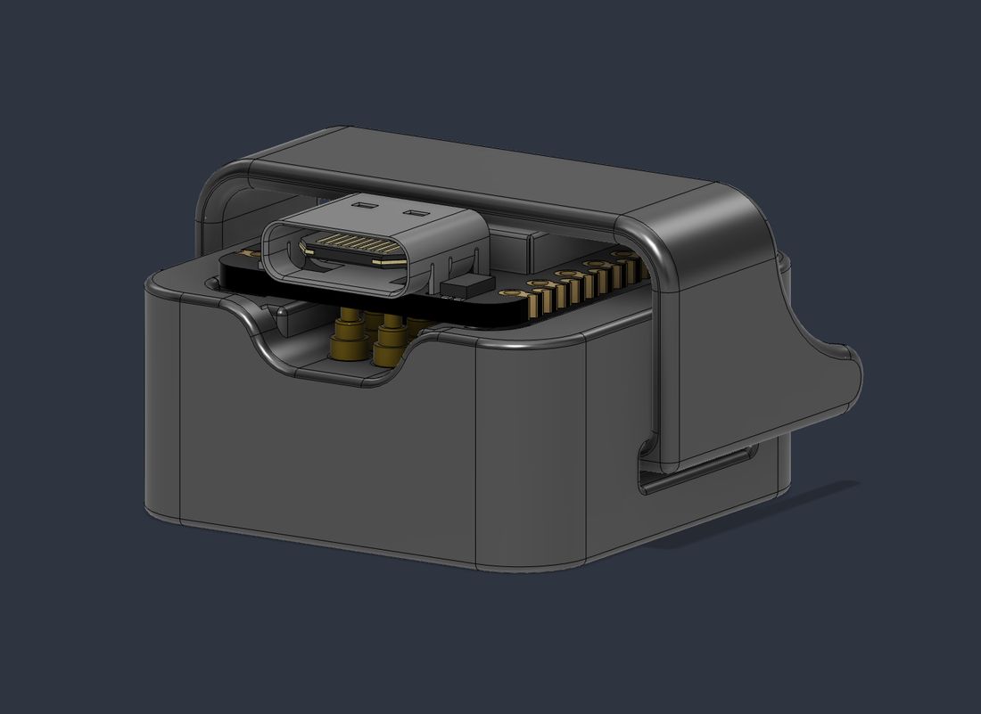
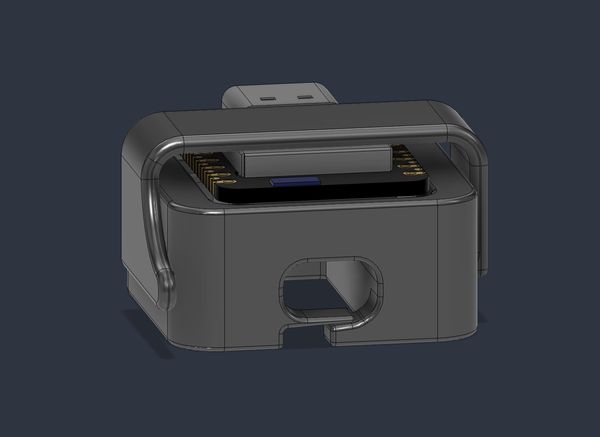
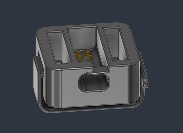
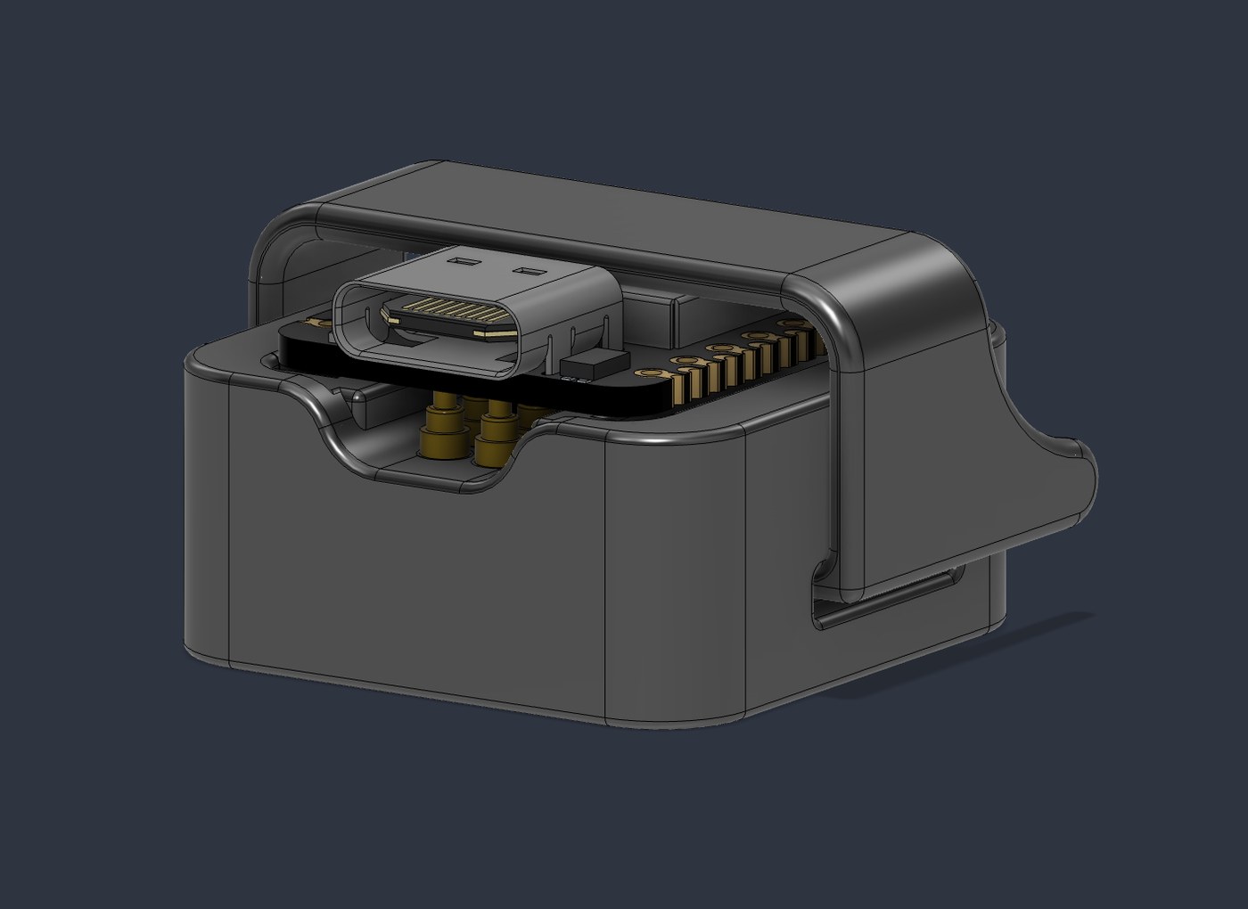
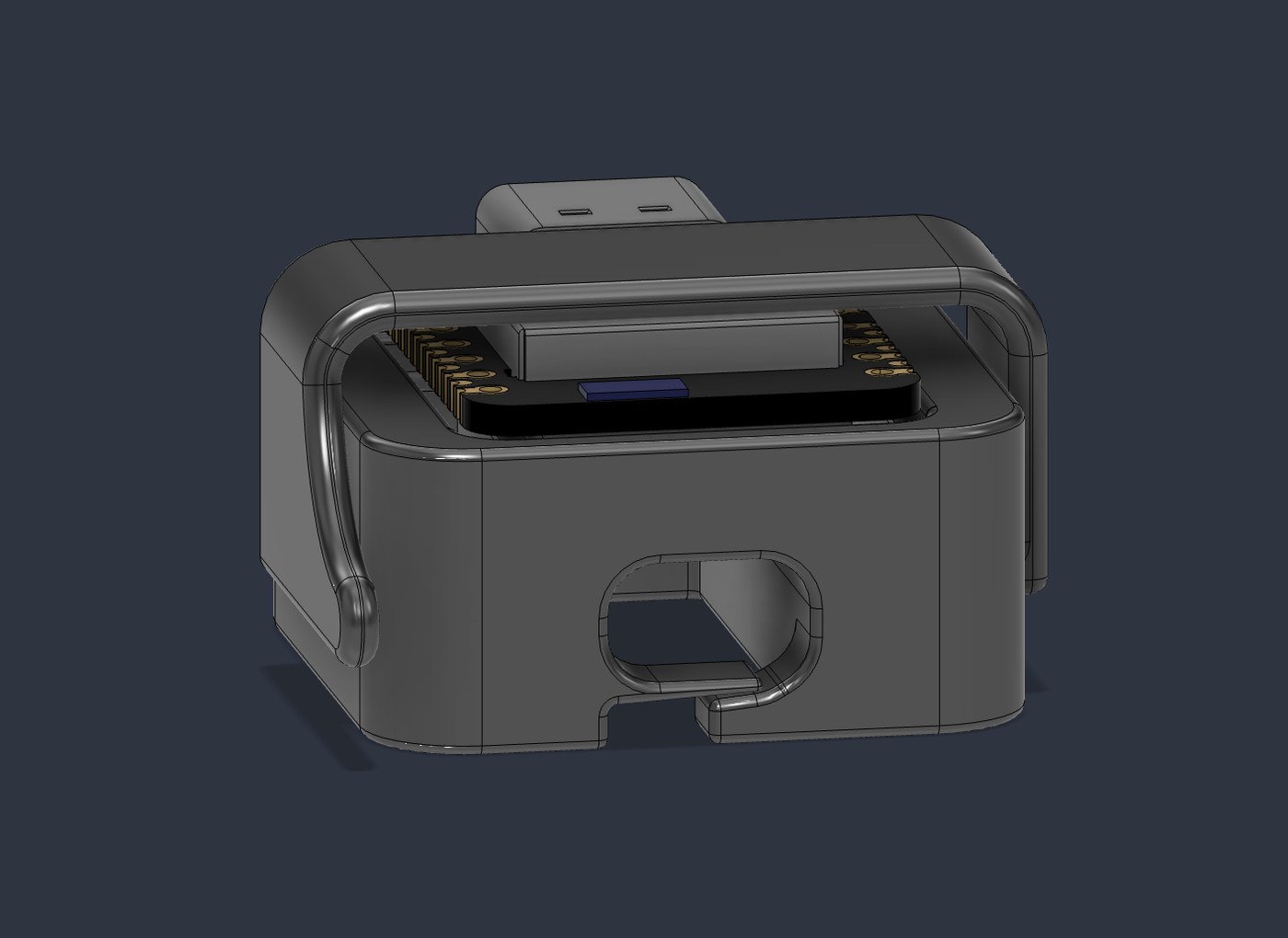
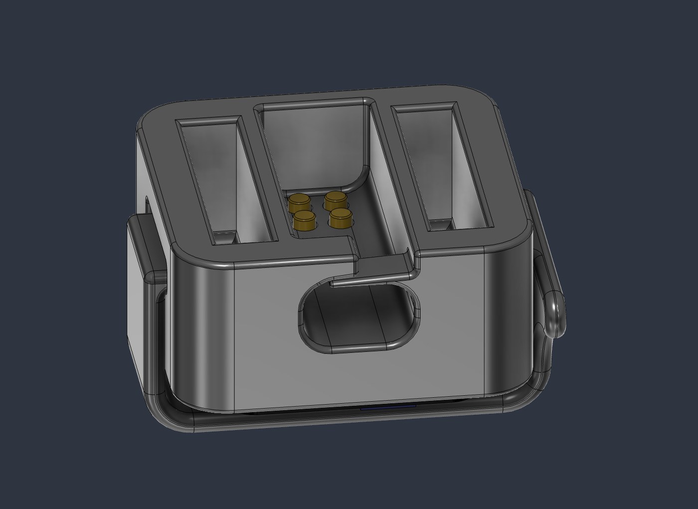
My first design was a holder that the Xiao would sit in and get clamped to. The clamp helped to push the Xiao board down onto the pogo pins that sat underneath. This worked well for a couple months, until it didn't. I wanted to debug another Xiao for Matter sleep states to optimise battery consumption. Turns out, I had to pull my whole setup apart just to get my holder back.
This is because the GPIO wires were connected underneath the holder, the XIAO couldn't simply be lifted out. Every board swap meant disconnecting all of the wiring first, which completely defeated the purpose of having a reusable debugging fixture. I could've redesigned it to have open sides so the wires could be slipped off, but then my clamp over the top wouldn't have anything to connect to. I decided to redesign it so it'd be easier to use.
The Redesign
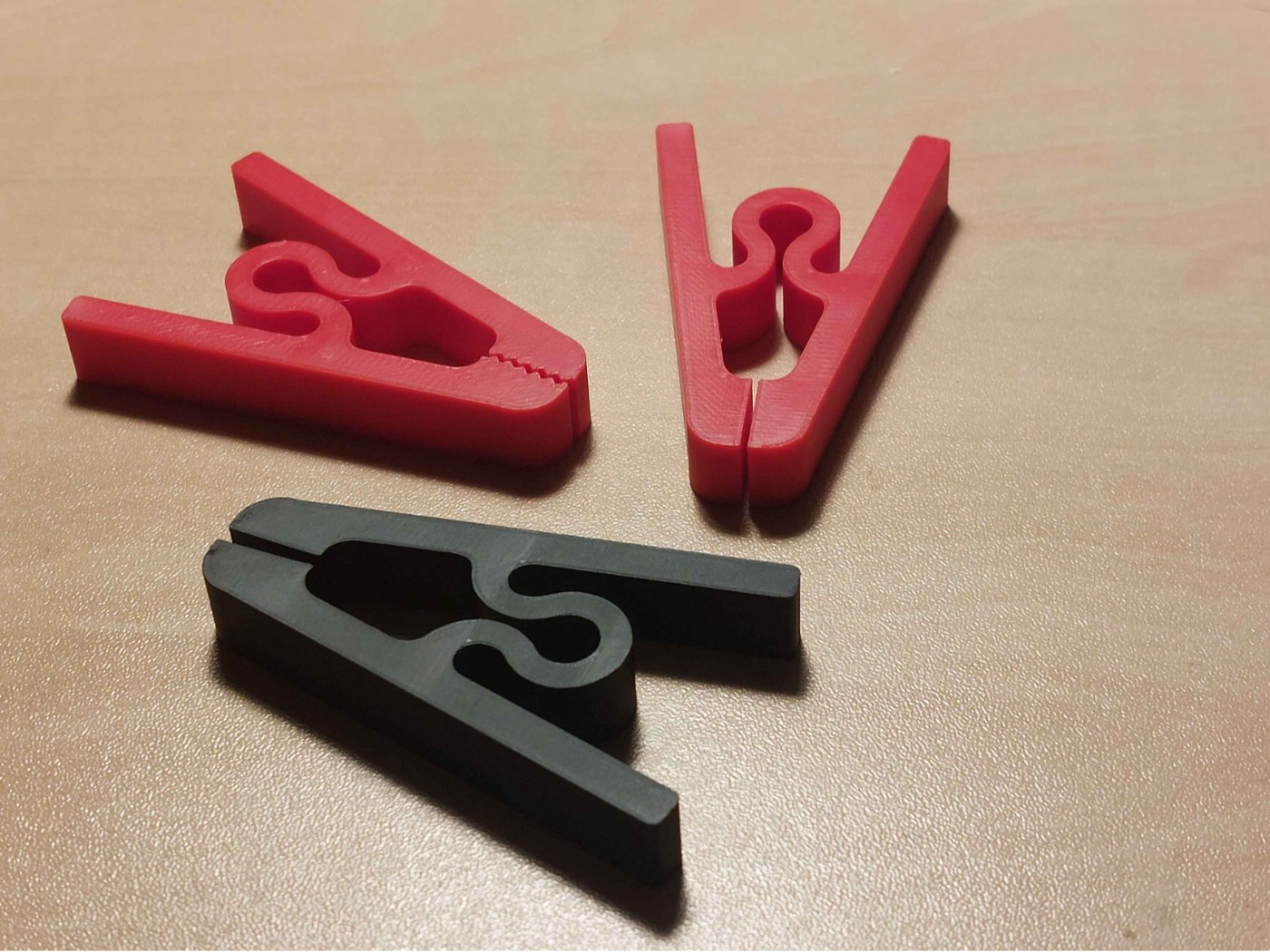
I began hunting on printables and makerworld for pegs. How do you even make a 3D printed peg? It was a lot easier than I thought. After seeing how I could make a peg, I began my development.
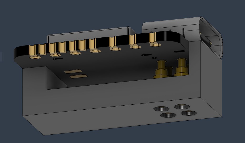
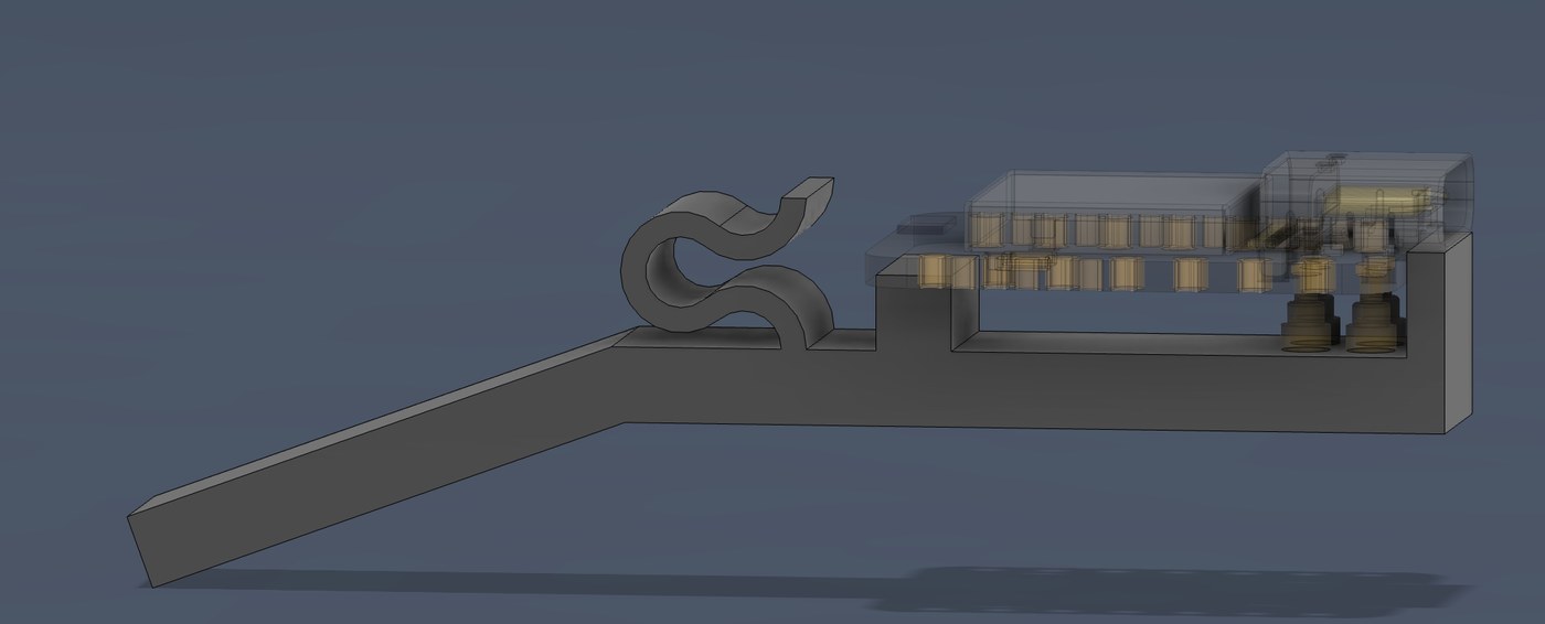
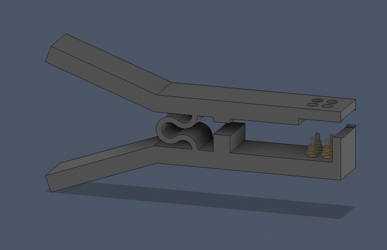
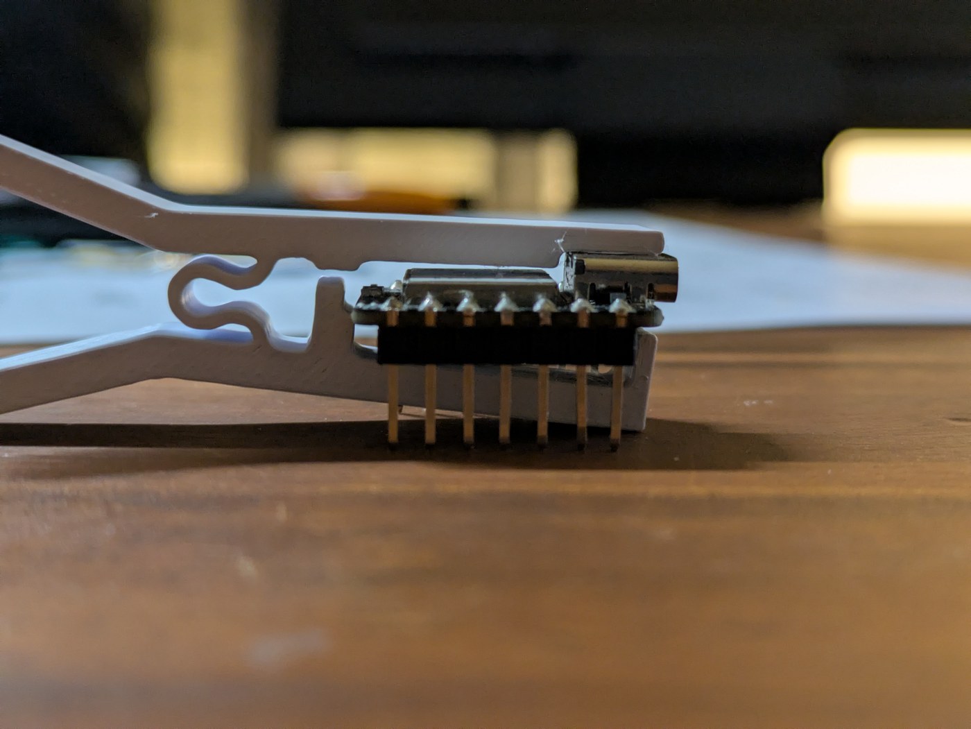
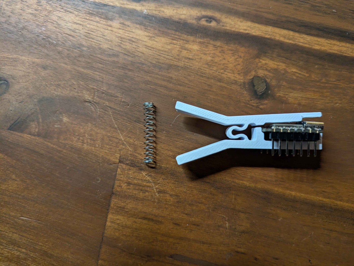
I quickly ran into an issue. The 3D printed "spring" wasn't able to provide enough clamping force onto the Xiao. The Xiao was able to lift up and move off from the pins. I had a pen spring sitting around and decided to put it to some use. On my first iteration with pins for the spring to sit on, the spring just kept trying to fly off.
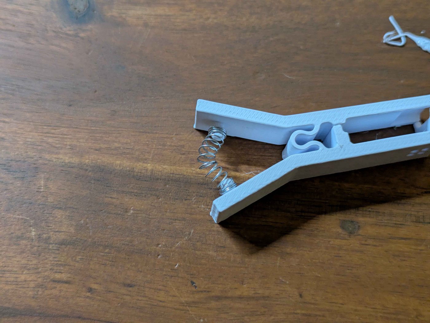
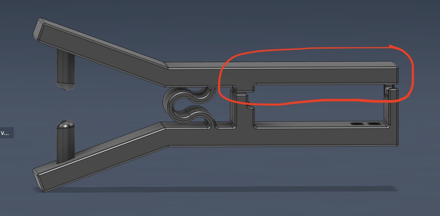
After extending the pins, the spring had less ability to flex outwards and the force was more so directed upwards. I then faced another issue. The top half of the clamp wasn't able to angle downwards, so the force was being distributed along the whole length of the Xiao board. The result of this was the Xiao not being pushed down onto the pins quite enough. My solution for this was to make the section circled in red thinner so it would sit higher above the Xiao and focus the force on the front of the Xiao board.
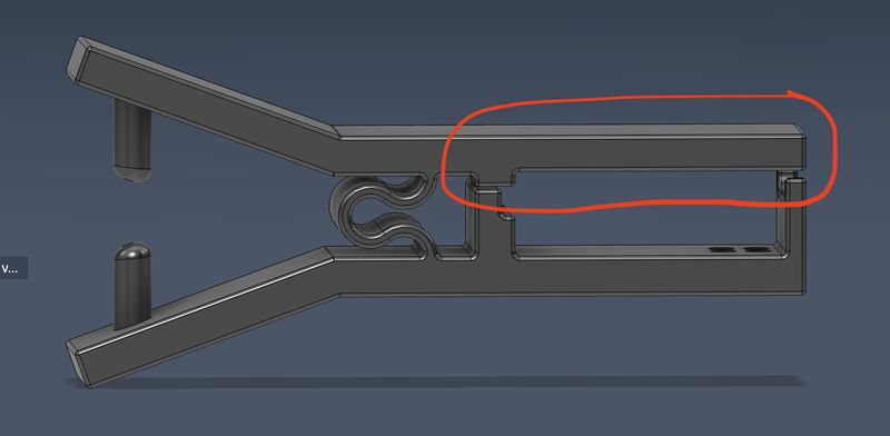
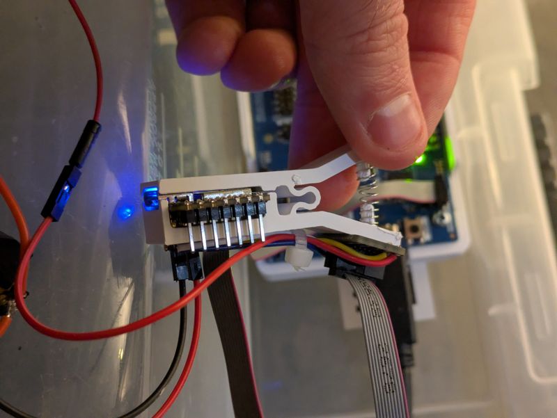
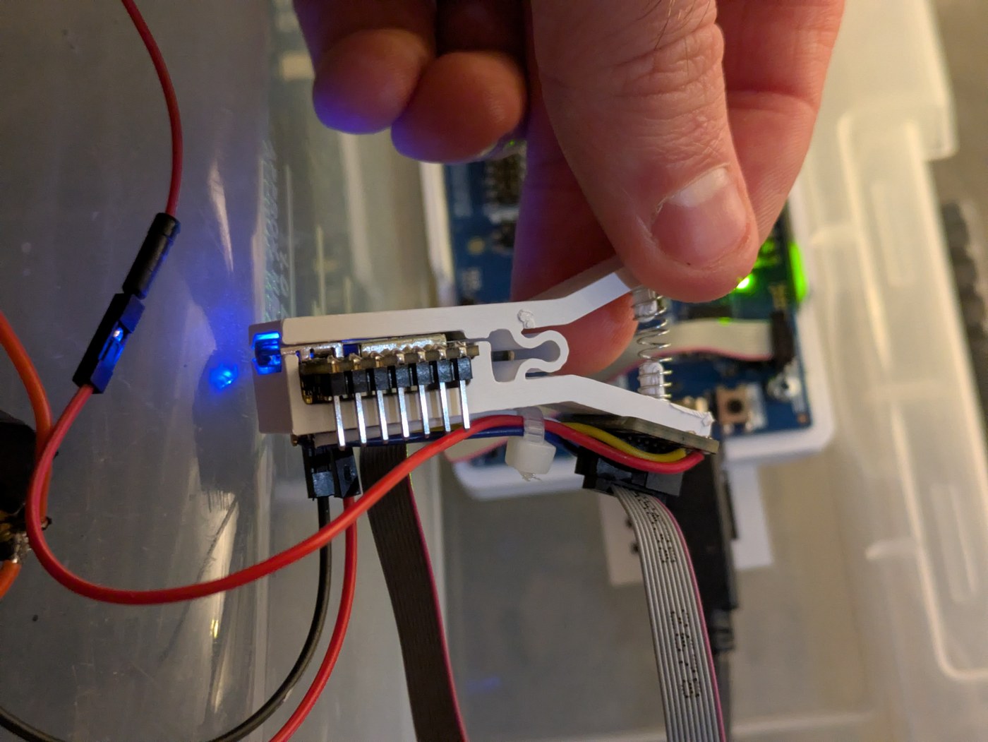
This adjustment worked allowing the pins to push down onto the JTAG pads of the Xiao.
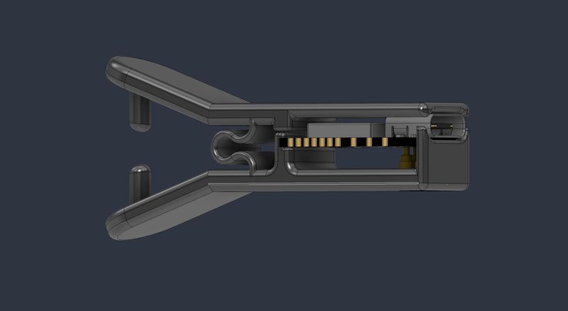
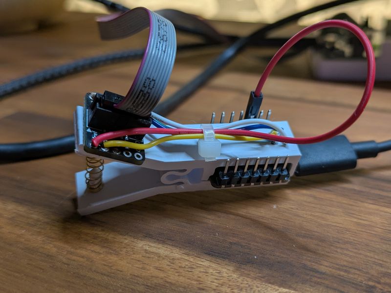
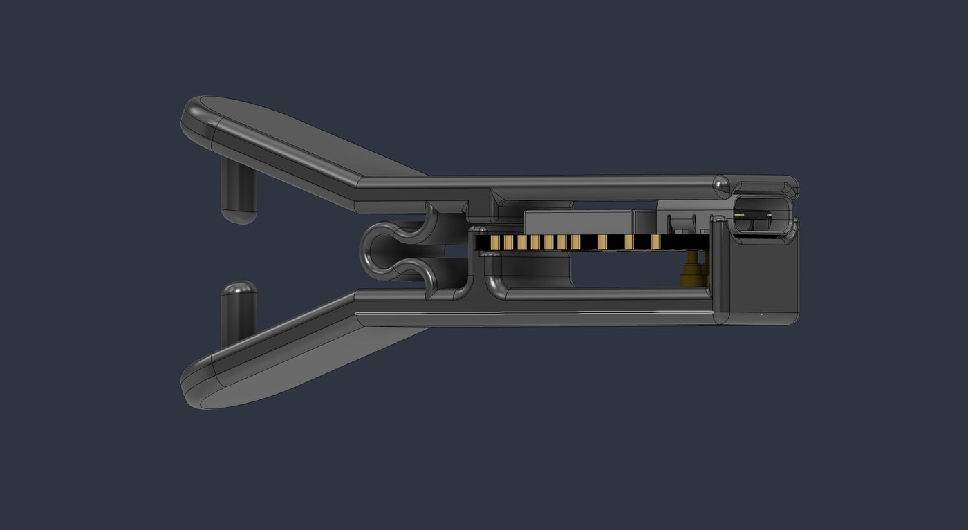
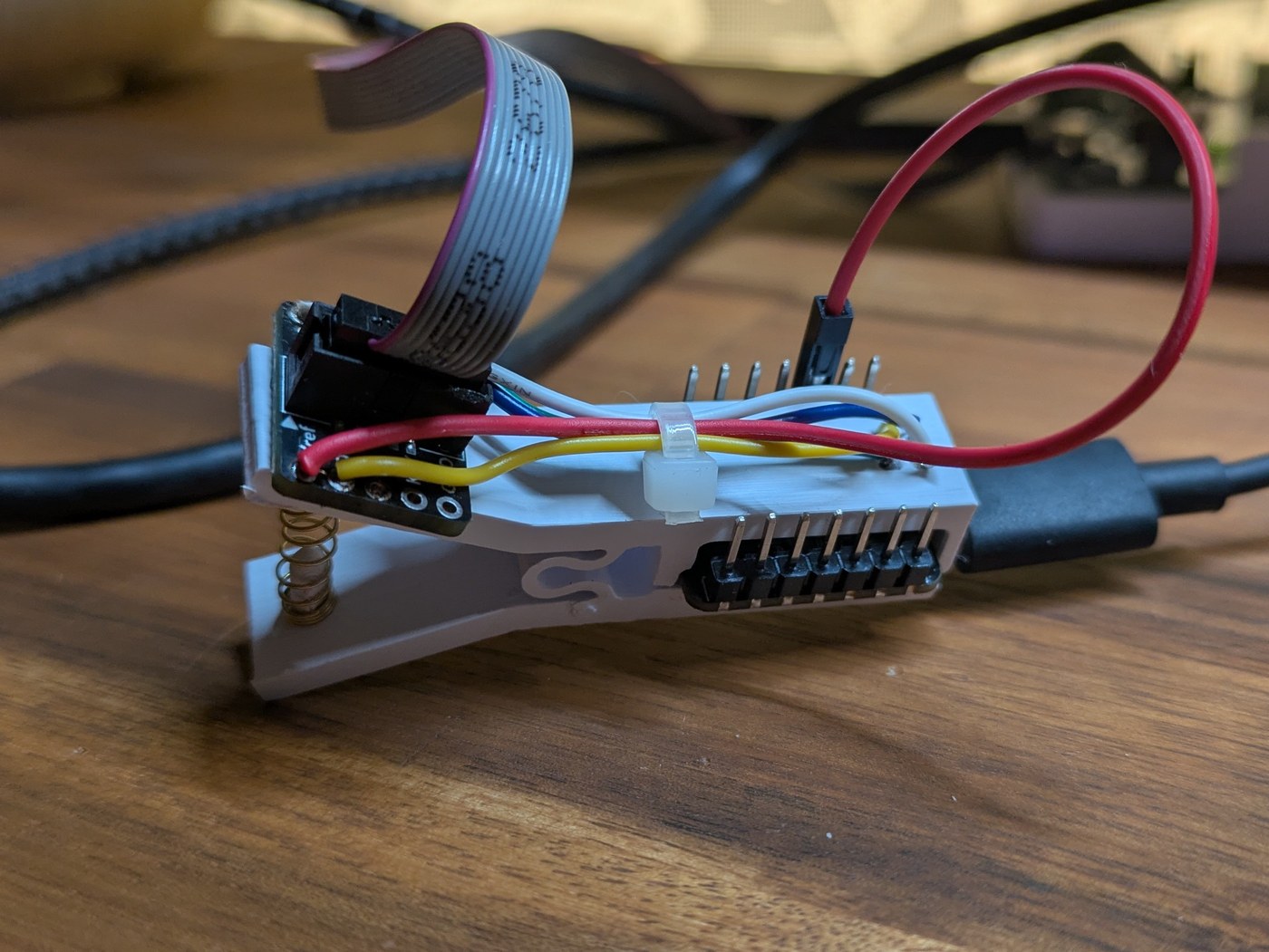
The new design is more like a peg where it has two halves connected together that push down on each other. At one end, we have a small pen spring because the original printed spring didn't provide enough clamping force. The printed spring is still retained, but now it simply keeps the two halves aligned while the pen spring provides the actual clamping pressure. At the other end, we are using the USB-C port on the Xiao as the alignment point. This keeps the GPIO pins accessible from both sides allowing the clamp to be removed at any given moment.
I've since refined the design and printed the updated version. I just haven't been motivated enough to desolder the existing wiring and install the pogo pins into the new clamp yet. I do have plans to design cable guides so a zip tie isn't needed as well as slots to hold the SWD breakout board. I've currently got the breakout board held on with Tesa double-sided tape, but I'd prefer printed slots.
Future Improvements
- Integrated SWD breakout holder
- Cable tie no longer required
- Replace tape with mechanical retention
- Better strain relief
Conclusion
Overall I'm much happier with this design. The clamp can now be removed without disconnecting the rest of the setup, making it significantly easier to swap between development boards during debugging. As always, the Fusion360 file as well as an STL file are both available for download in the files tab.